I live in Houston and over the years I’ve built a descent outdoor kitchen and entertainment space. Although it’s HOT-AS-HELL in the summertime, we are fortunate to be able to use the space year round.
Now that I’ve gotten into homebrewing, the next upgrade for this space is a tap-wall. We have a detached garage and the side of the garage borders our outdoor living space. I’m building a 6-tap wall-mounted tower that has been inspired by this thread.
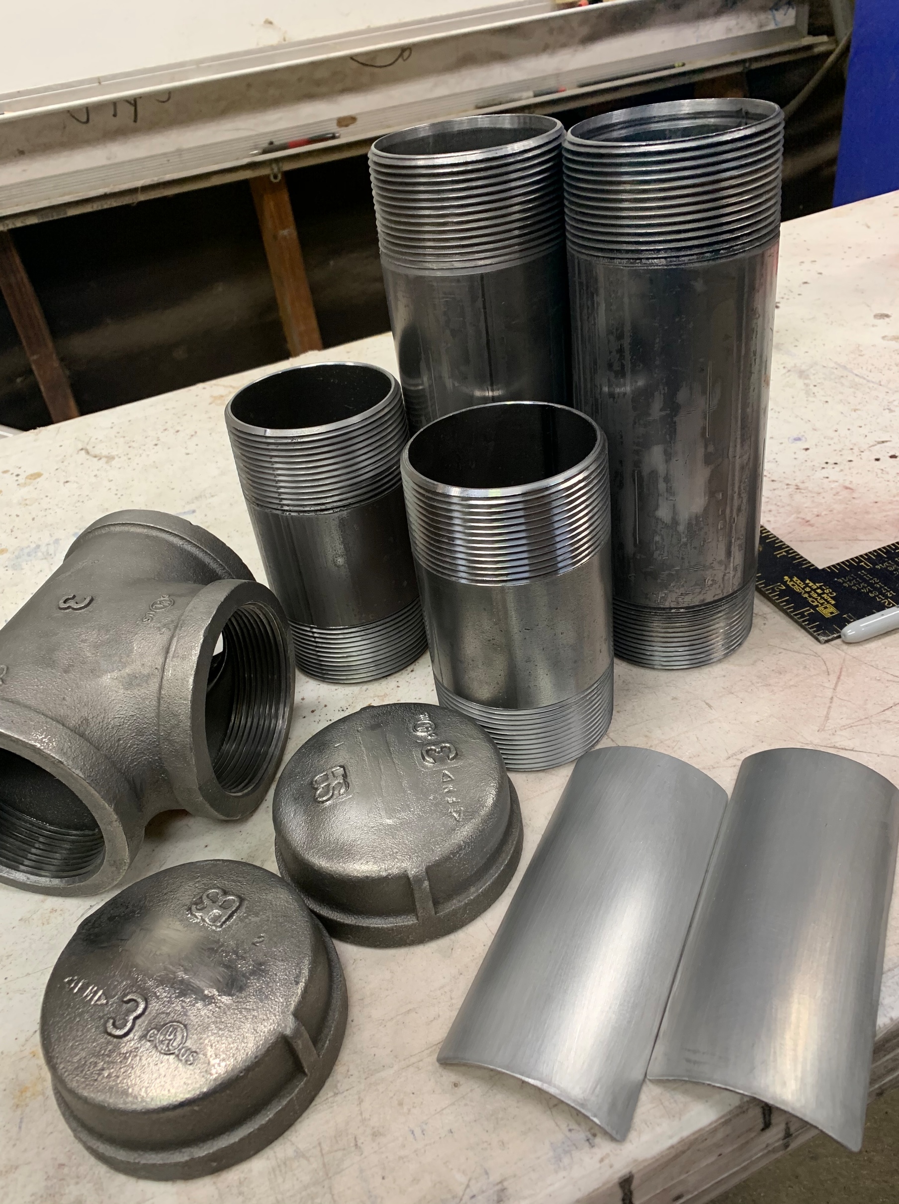
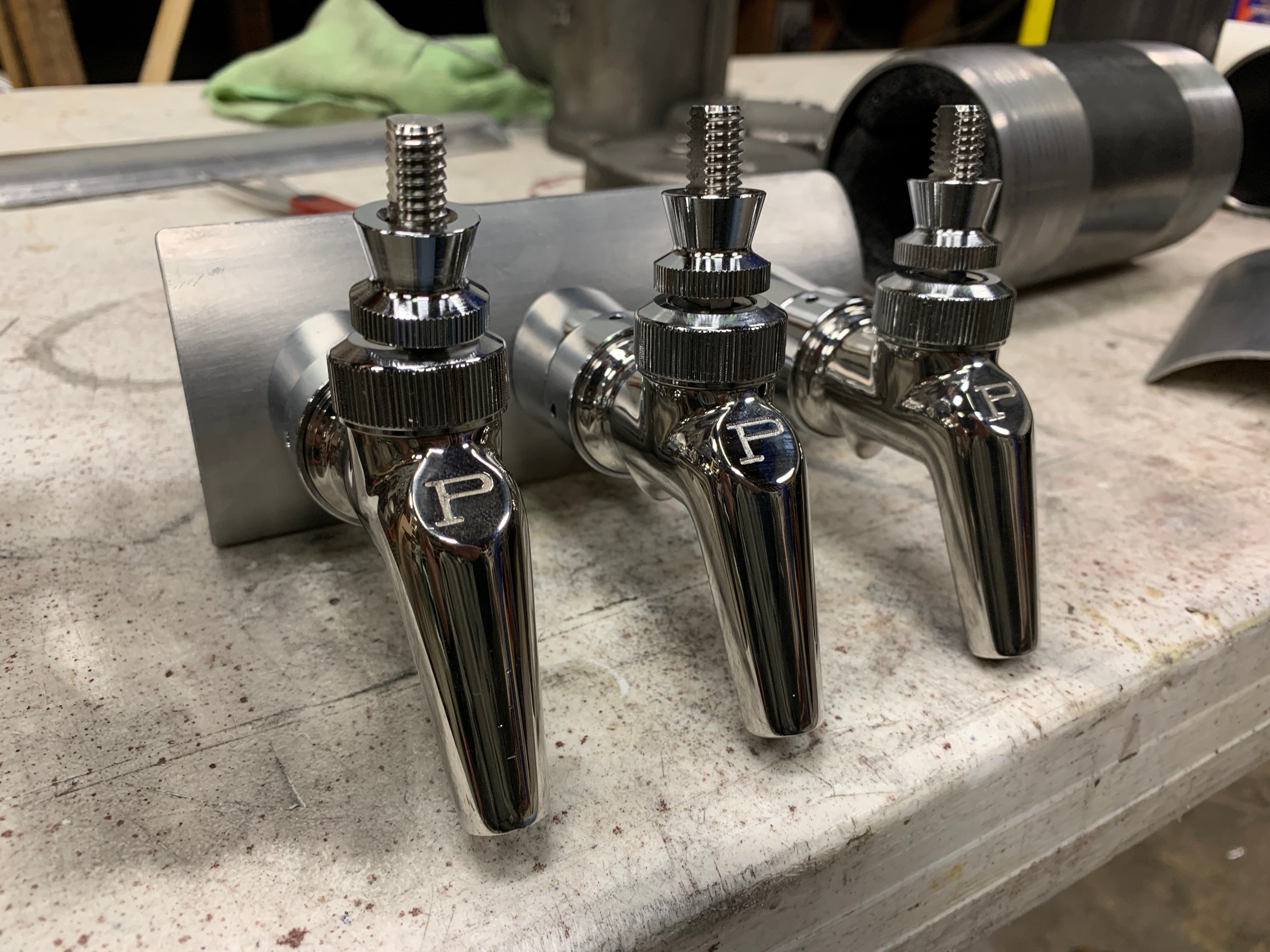
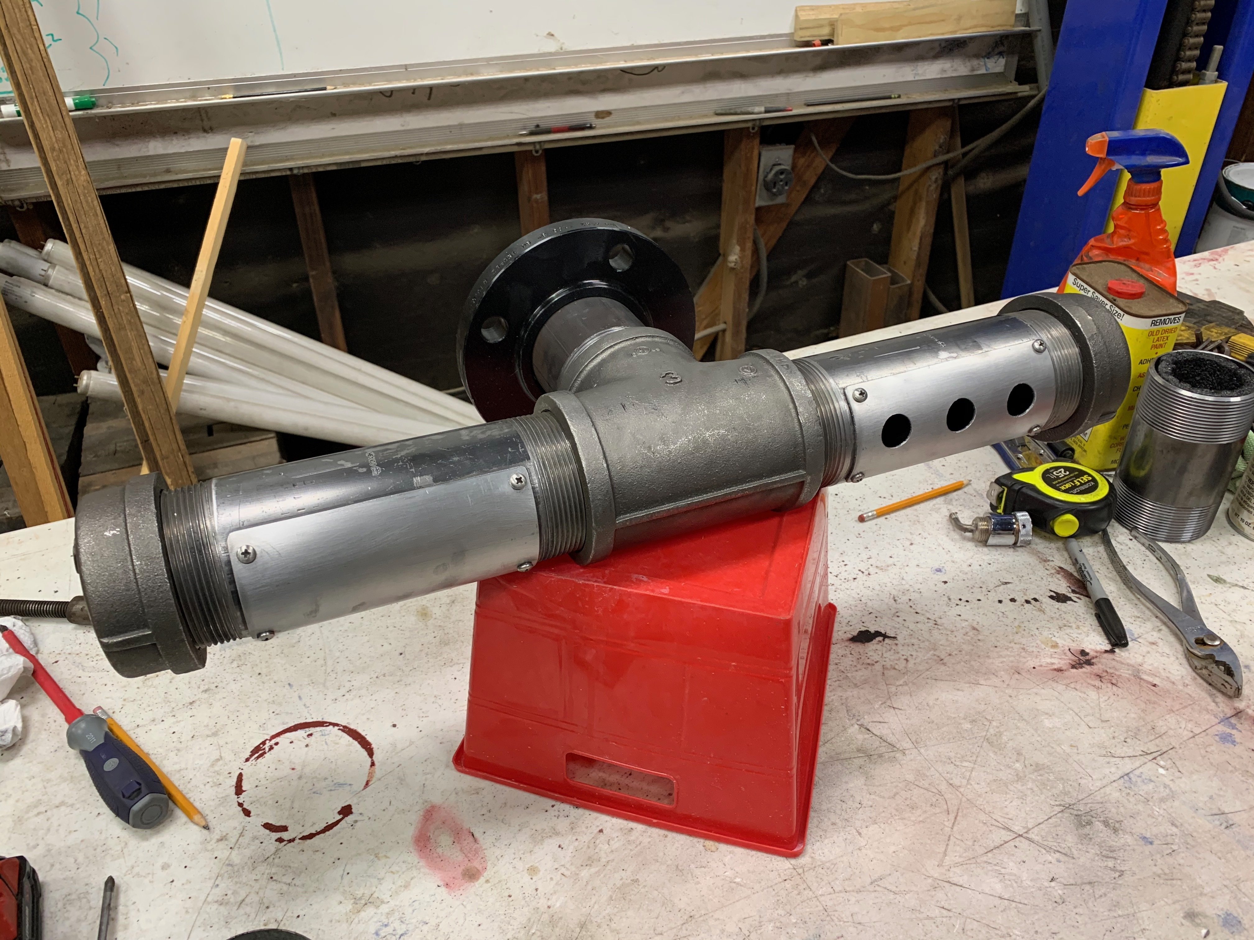
My set-up will be a “T” with three taps on each side that is wall-mounted (so not really a ‘tower’). Here are the parts I’m prepping.
I’ve found a small 53 CFM blower fan on Amazon to use as my tower cooler so I’ll run a line (3/4" or 1") from the blower to inside the black-pipe tap tower to recirculate the chilled air from tap shank(s) to the kegerator and keep everything cool.
Anyone have any suggestions or comments based on their experience? I only want to build this thing once I’m hoping that fan will push enough air and the flexible duct has a high enough R value to keep everything cool.
That’s going to be pretty rad! My buddy did a something similar, but through a wall in his basement.
Definitely consider insulating the tower like the linked thread. If you’re pushing air in with the 3/4" or 1" line, it would probably help if the positive pressure inside the tower forces air back into your kegerator via the 4" duct for recirculation.
My hope is that the fan I’ve selected has enough pressure to blow thru a 3/4" hose all the way up to the tap shanks and have enough residual pressure (is that a thing?) to push the air back down the duct to the kegerator. That is the only way to get actual ‘re-circulation’ and keep things cool from end-to-end.
This ‘recirculation system’ is one of the big design elements that I’m looking to get feedback on…has anyone done it this way? Will it work as expected? Is there a better solution (or fan…or insulation…)?
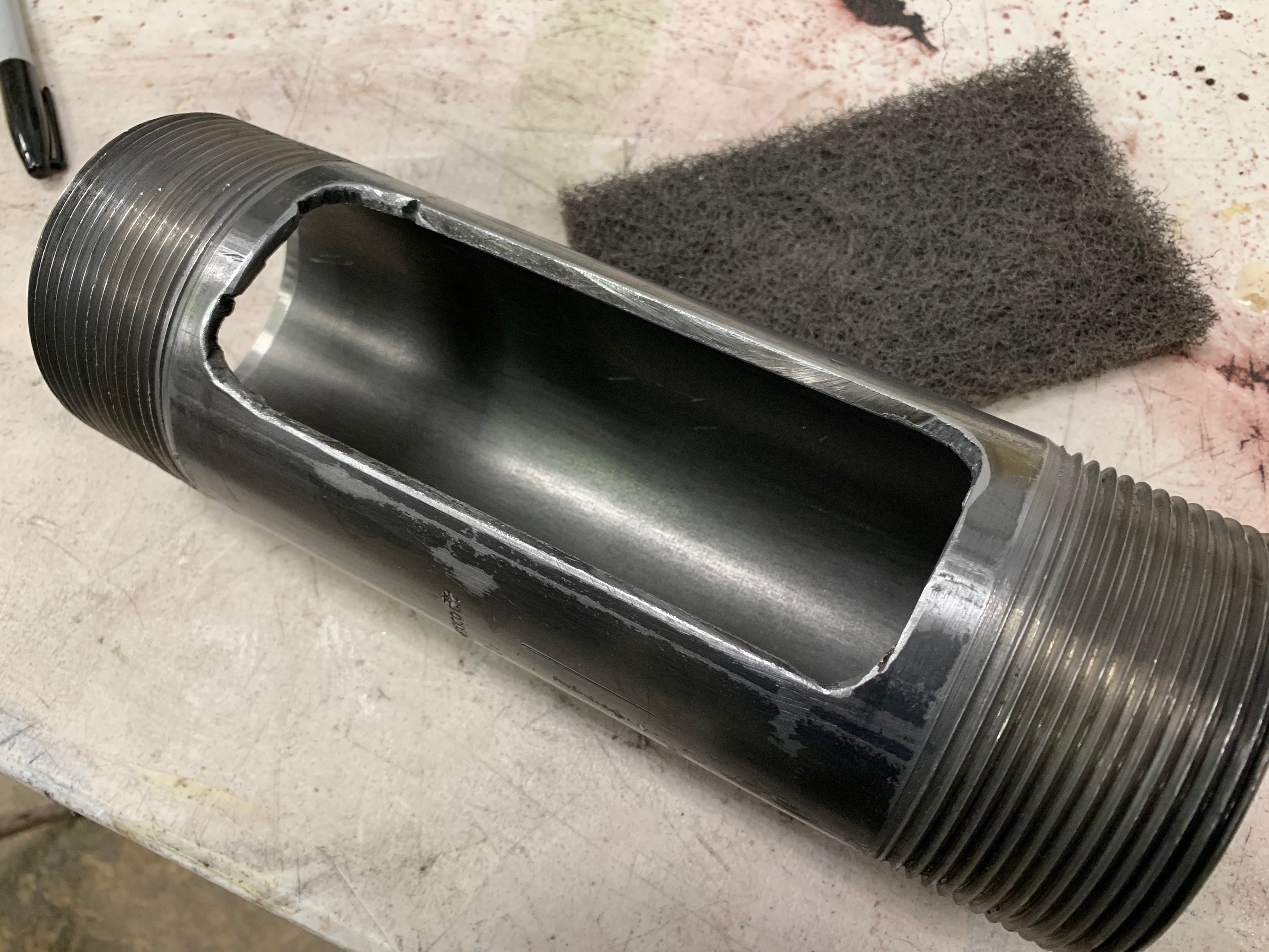
I’ve already started mocking-up the interior insulation for the black pipe…this is just pipe insulation that I’ve cut and split to hug the inside walls of the pipe. I believe this will do the trick.
My buddy has four beer lines going through a 4" flexible duct (which acts as the air return), and a 120mm fan pushing through another 4" flexible duct. His is feeding a big insulated box in the wall though.
Are you planning on feeding everything through the 4" duct?
Yes - I’m planning to feed everything thru the same 4" flexible duct. The limiting factor is the 3" black pipe that the faucets are mounted. In my mind (and anyone let me know if you disagree) I’m not sure there is an advantage to running multiple 4" lines (one for cool and the other for return) if the tower is only 3".
Here is my math:
The ‘tower’ made from 3" black pipe has an interior cross section area of ~7 square inches
A liquid line 3/16 ID - 7/16 OD has a cross section area of .2 square inches
6 liquid lines would take 1.2 square inches of space (6x.2)
The cooling hose (from the blower to the shanks) would be 1.25" OD which is a cross section 1.2 square inches of space
Add that up and you have about 2.5" of ‘space’ being used by the 7 different hoses (6 beer and 1 cooling)
That would leave about 4.5 square inches (more than half the total area) of unoccupied ‘space’ for the return air in the black pipe (and much more in the 4" flexible duct) to ‘blow’ back down the the pipe and duct into the kegerator.
My tower utilizes a “T” design so the air has to travel in and out of the same “base”. If I had utilized a “U” design I could have had the cool air going in on one side and exiting on the other. In retrospect that would be easier (for cooling)…but it is not the aesthetic design I wanted.
This is the basic design (but the left/right sides are almost double the length that what is pictured)
Our commercial kegerator has an air-cooled tower, and I can feel the cold air falling back down into the cabinet space with an even smaller opening.
The difference here is the kegerator is already air-cooled and has plenty of air circulation, as opposed to a converted freezer. This is where the double duct helps circulate air, but I think you’ll be fine.
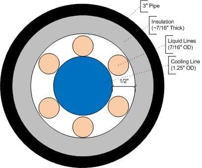
This sounds like an awesome idea. If I understand your dimensions above, it will look something like this inside the upright pipe.
In the Texas summer heat, you are going to need to move plenty of cold air all the way to the outer taps and back. Are you planning to T the cooling line and run out to the outer taps at both ends?
You may want a blower rather than a fan since it would provide more positive pressure to drive the air in through the cooling tube, back out through the pipe and back to the kegerator. It would also be good to keep all the lines reasonably straight so that air flow coming back is less restricted.
I’ve never done this - just trying to offer some thoughts that might be helpful.
Good point on getting the cooling air to each end of the ‘T’
I was just browsing the Micromatic site, and noticed their blowers for air cooled systems: Their 51 CFM blower is recommended for up to 15 ft. of line length. Based on that, I was thinking the model @Tripod linked to should be sufficient?
Nice design. Is this going to be your main feed to your taps or just for parties? I have my insulated taps running through an interior wall and although not as warm as a Texas summer gets warm In the summer. My lines are about 5 or 6’ long. I’ll fill a small glass and dump it. I’m sure you’ll be fine with only 8’. It would be more of a concern for a longer line. When I tended bar and we had a 20’ run I always dumped the line wah
@voltron - My kegerator is a commercial True back-bar fridge so it has plenty of air circulation as you noted. However - I’ll still need the blower…thanks for doing the cross-reference on the CFM of the Micromatic. I did not find that data - So I feel a little better about the blower I’ve picked.
@Steve - I love the diagram! That is exactly what I’m doing. And what you’ve represented is the most ‘constricted’ it will be (only the length of the ‘base’ of the tower). Nice catch regarding a t-fitting to split the cooling line - That is exactly what I was planning to do! The fan I picked is definitely a blower-style for the exact reason you mentioned. Your comments and suggestions are greatly appreciated. Seem we’re thinking about it the same.
@brew_cat - This will be my main feed. My kegerator holds two 1/2 barrel kegs so it’s not small or portable (no plans to put it on rollers). The tower will be permanently wall-mounted and it’s available 24/7/365…not just for parties
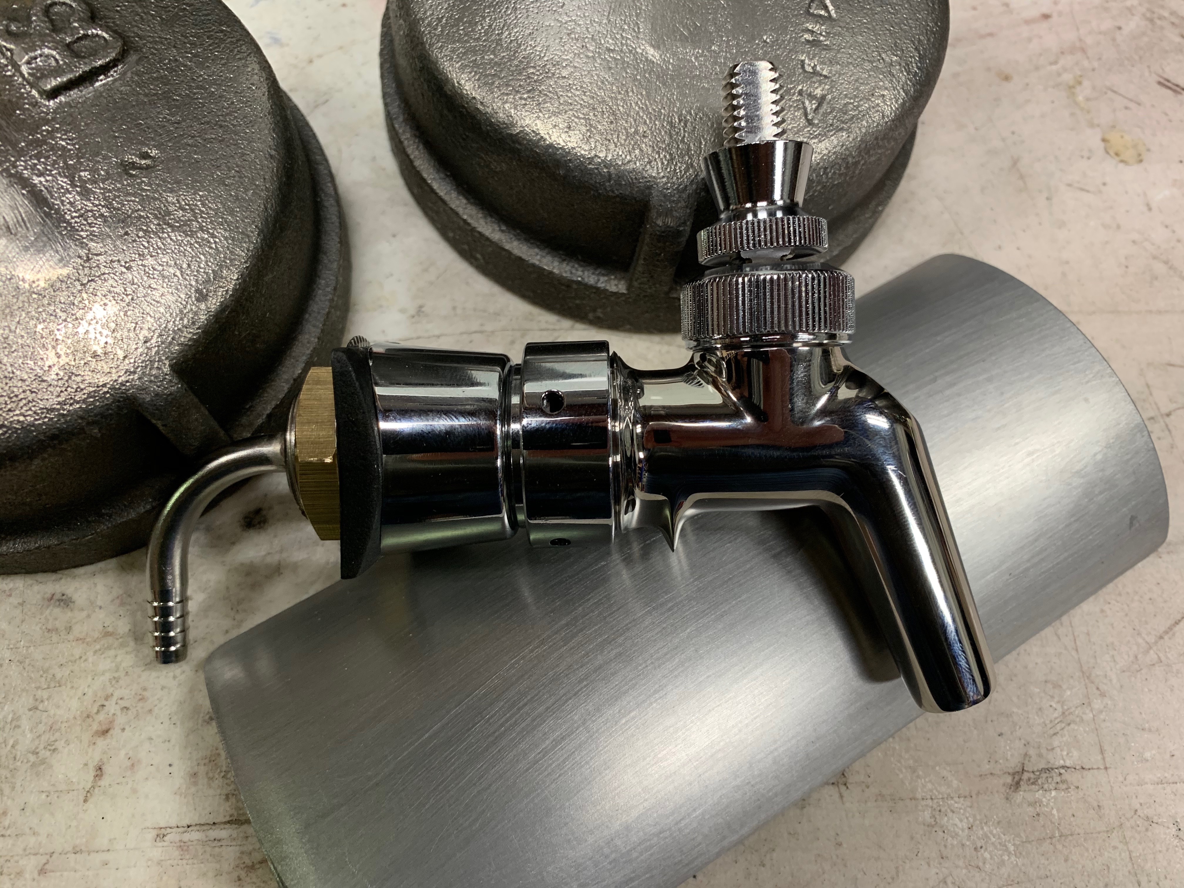
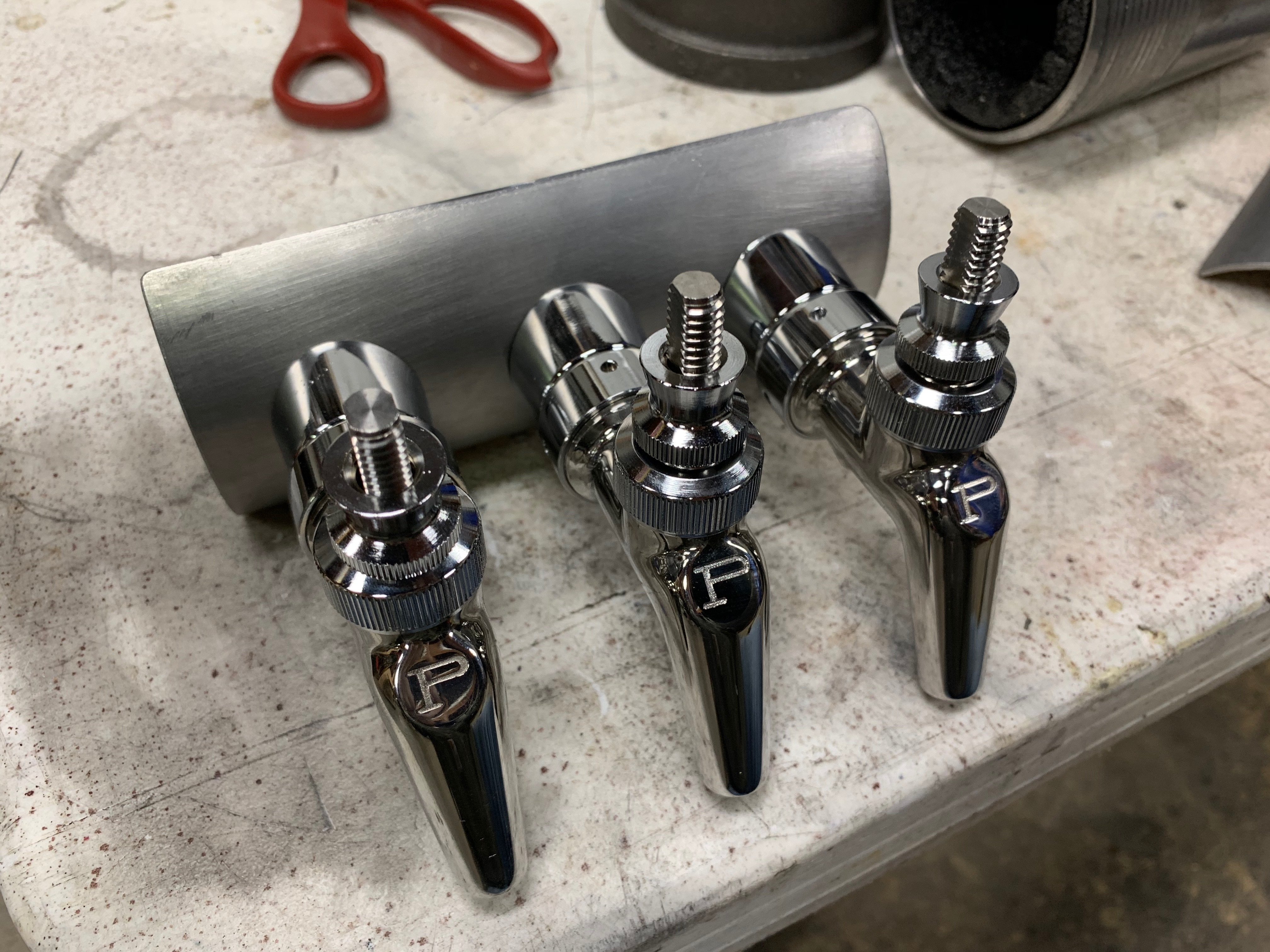
I got half my stainless steel shanks and faucets so I spent some time test-fitting this stuff. Here’s some beer tap porn:
I made some progress last night and snapped some pix. Still a long way to go…
Originally I was going to populate the one side with three faucets and add the other 3 faucets in the future. However, after further reflection…it will be so much easier just to run the liquid lines now and not try to fish them thru in the future. So…I’m going to do all 6 liquid lines and shanks now. I’ll add the last 3 faucets in the future. I found these to cap the faucet-less shanks: https://ajexusa.com/product/121220-faucet-shank-plug-chrome/
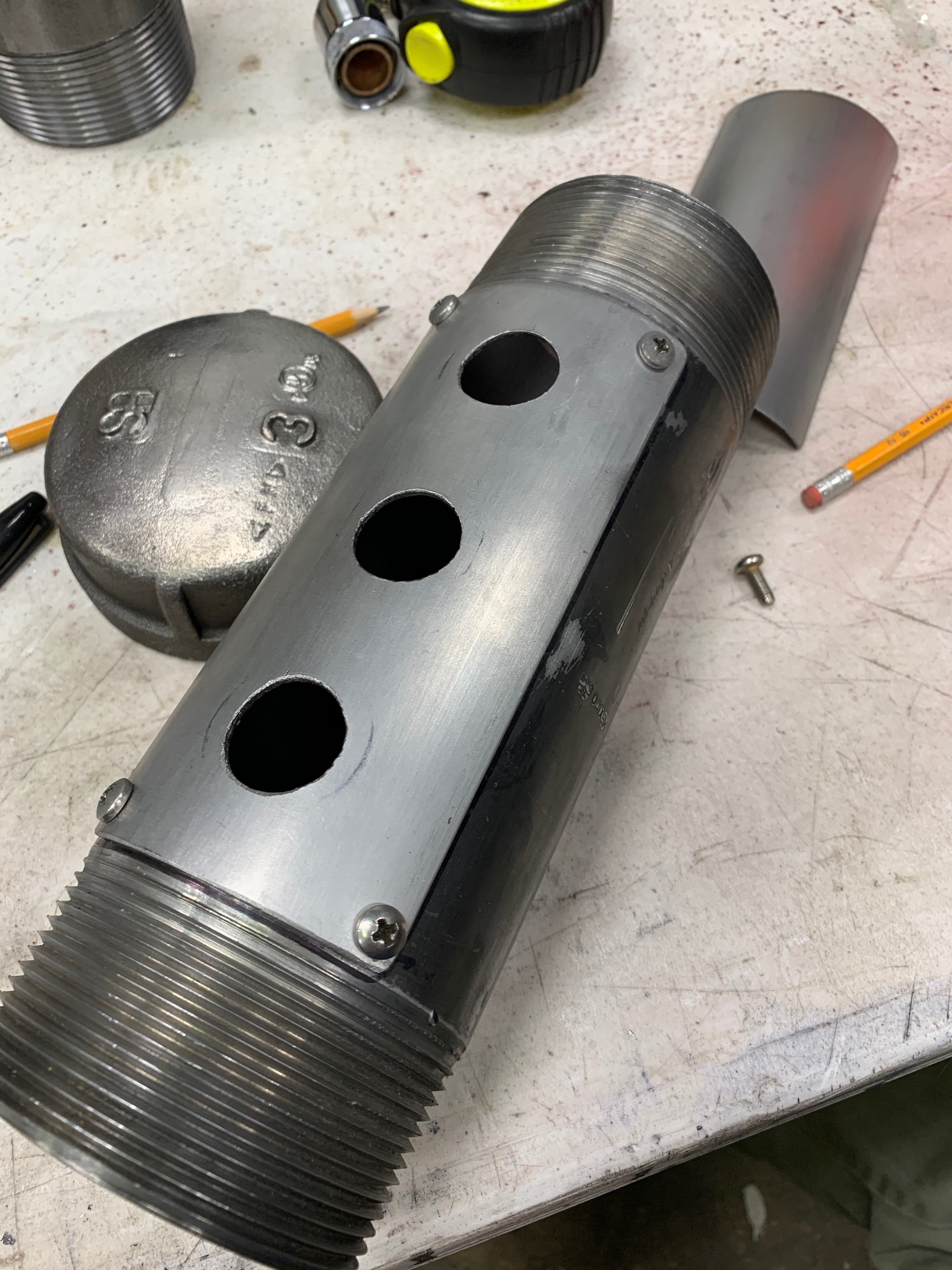
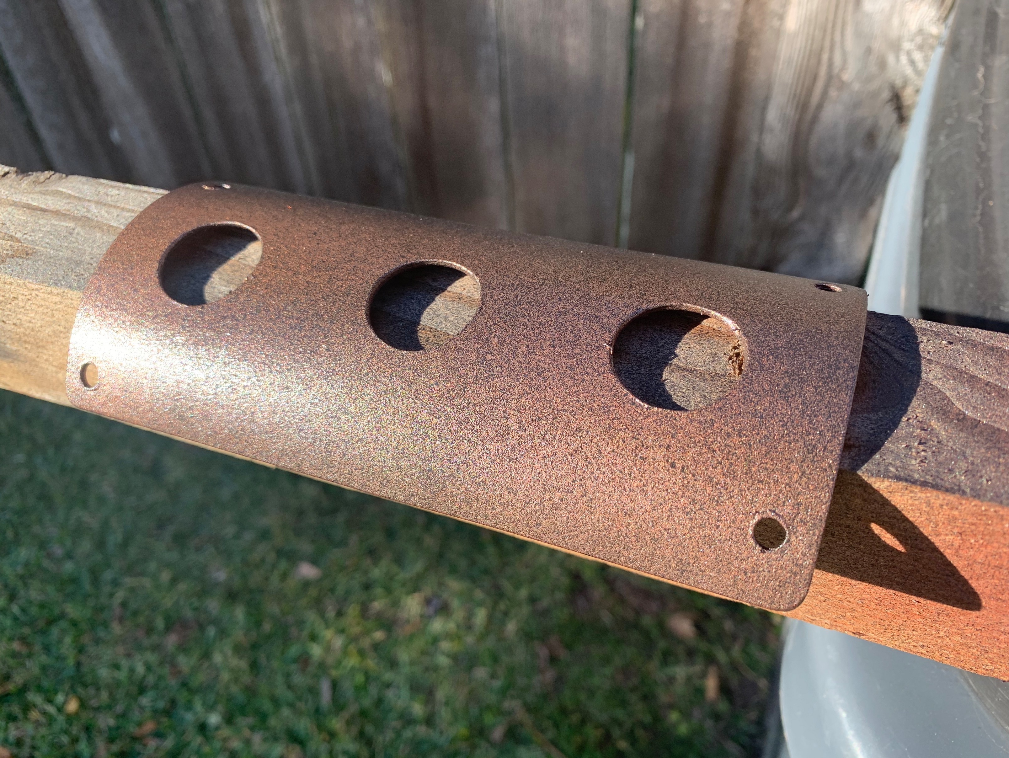
Cutting the window for the faucet faceplate
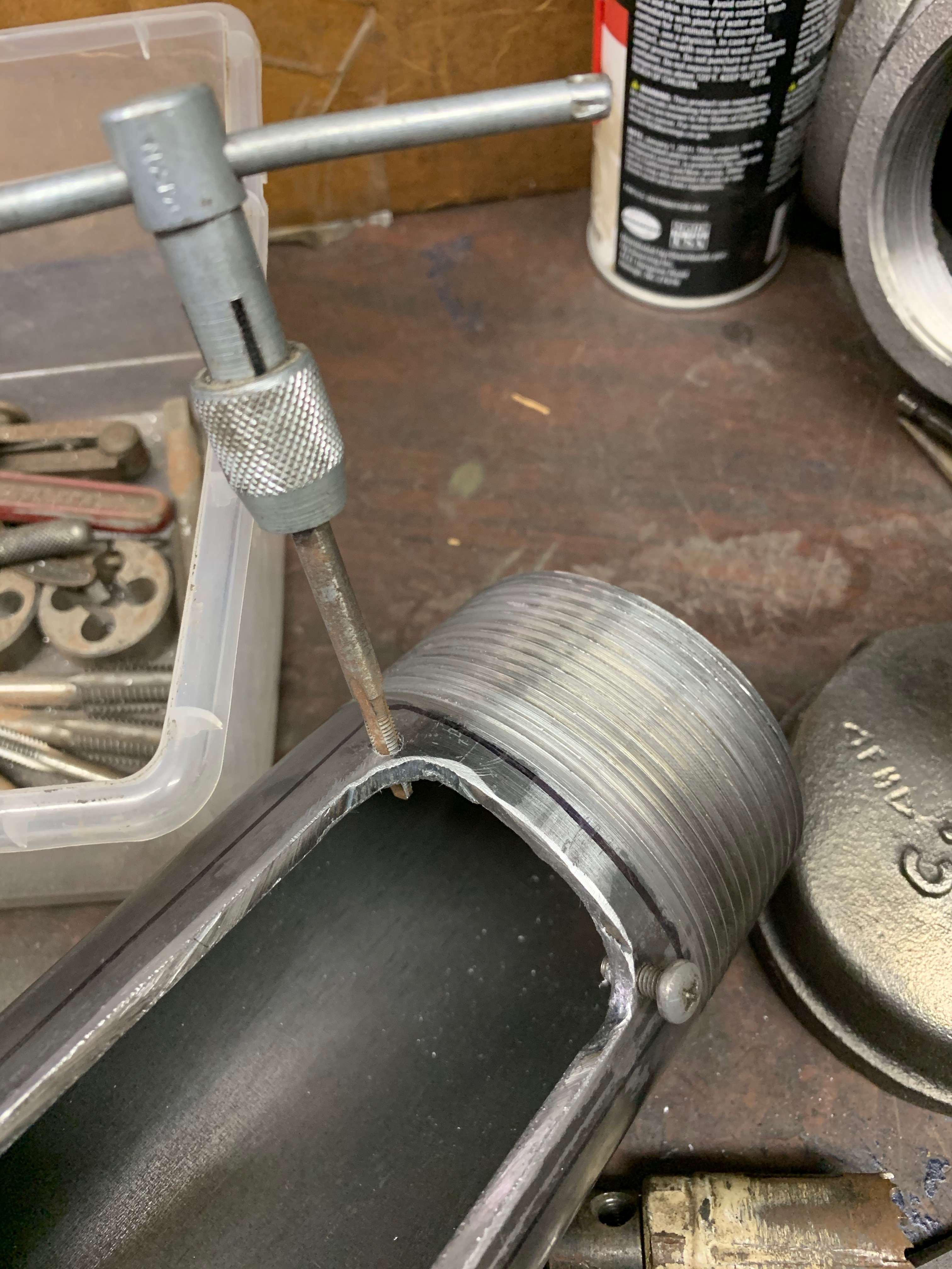
Tapping to be able to screw the faceplate to the pipe
Test fit - yummy!
Faucets removed…test fitting with faceplate screwed on
Another view
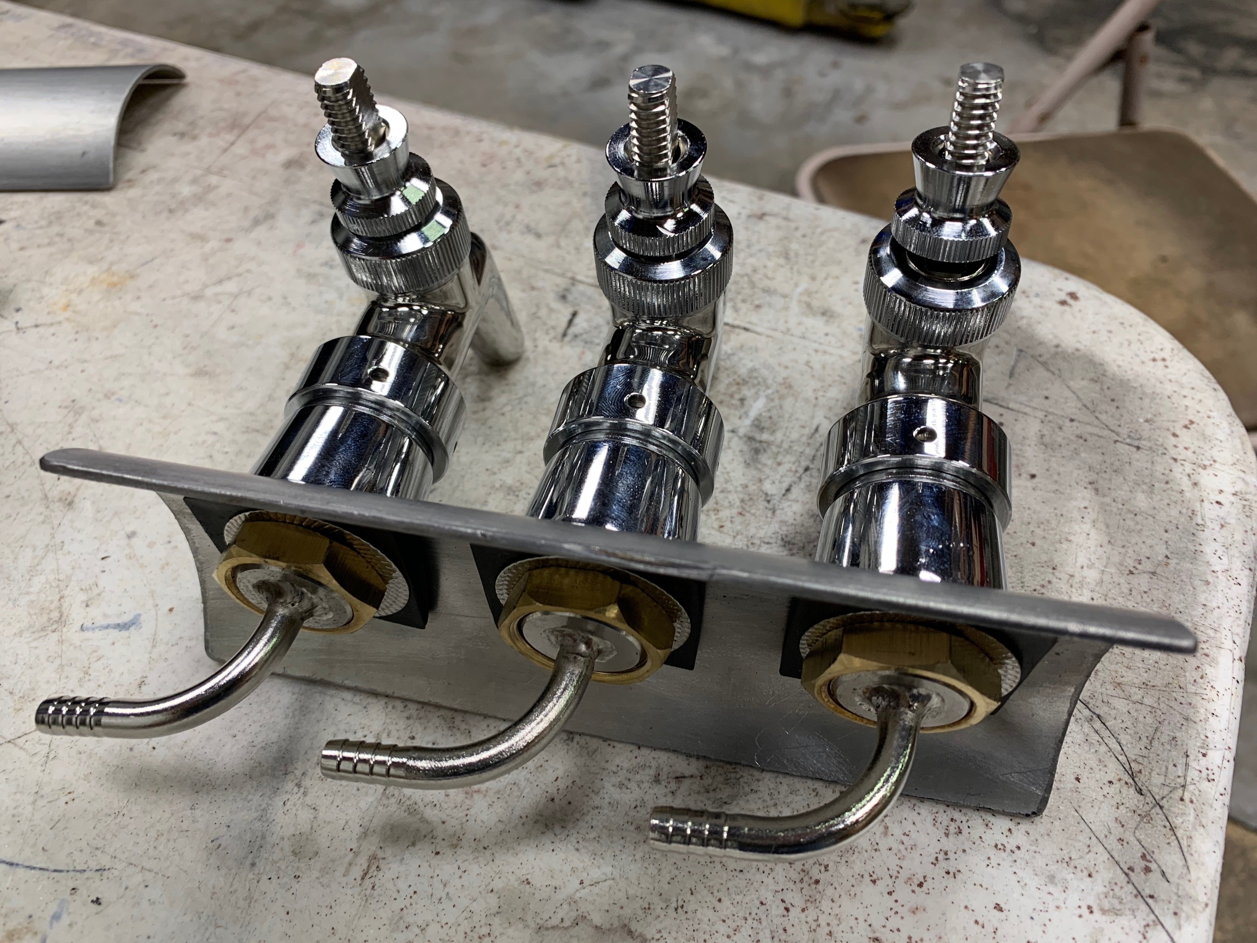
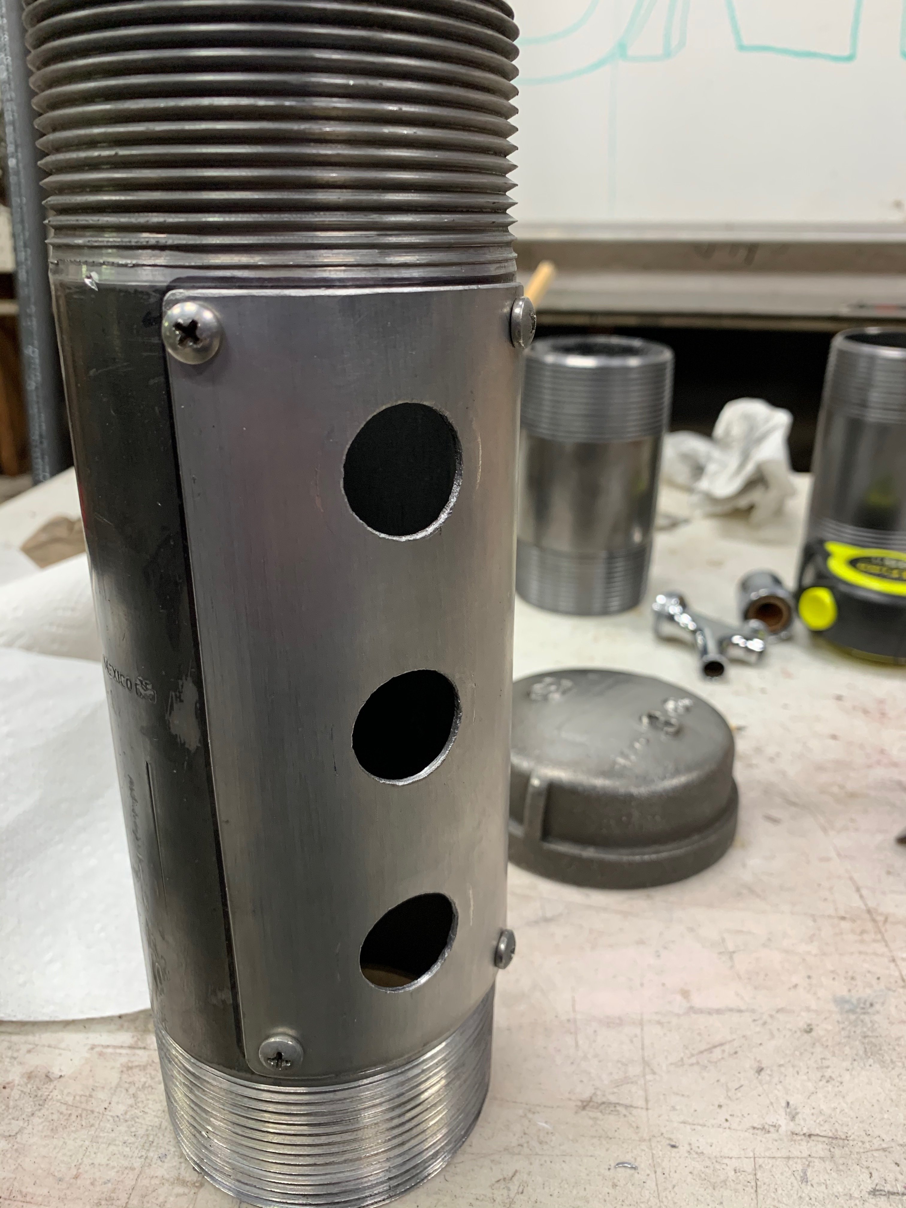
Test fitting the whole thing. The ‘window’ is already cut behind the faceplate on the left…just need to cut the holes for the shanks now
Be great to see all 6 pouring beer at the same time! I can appreciate your dedication dreaming this project up, testing the fitment and building… Keep the “tap porn” coming! Sneezles61
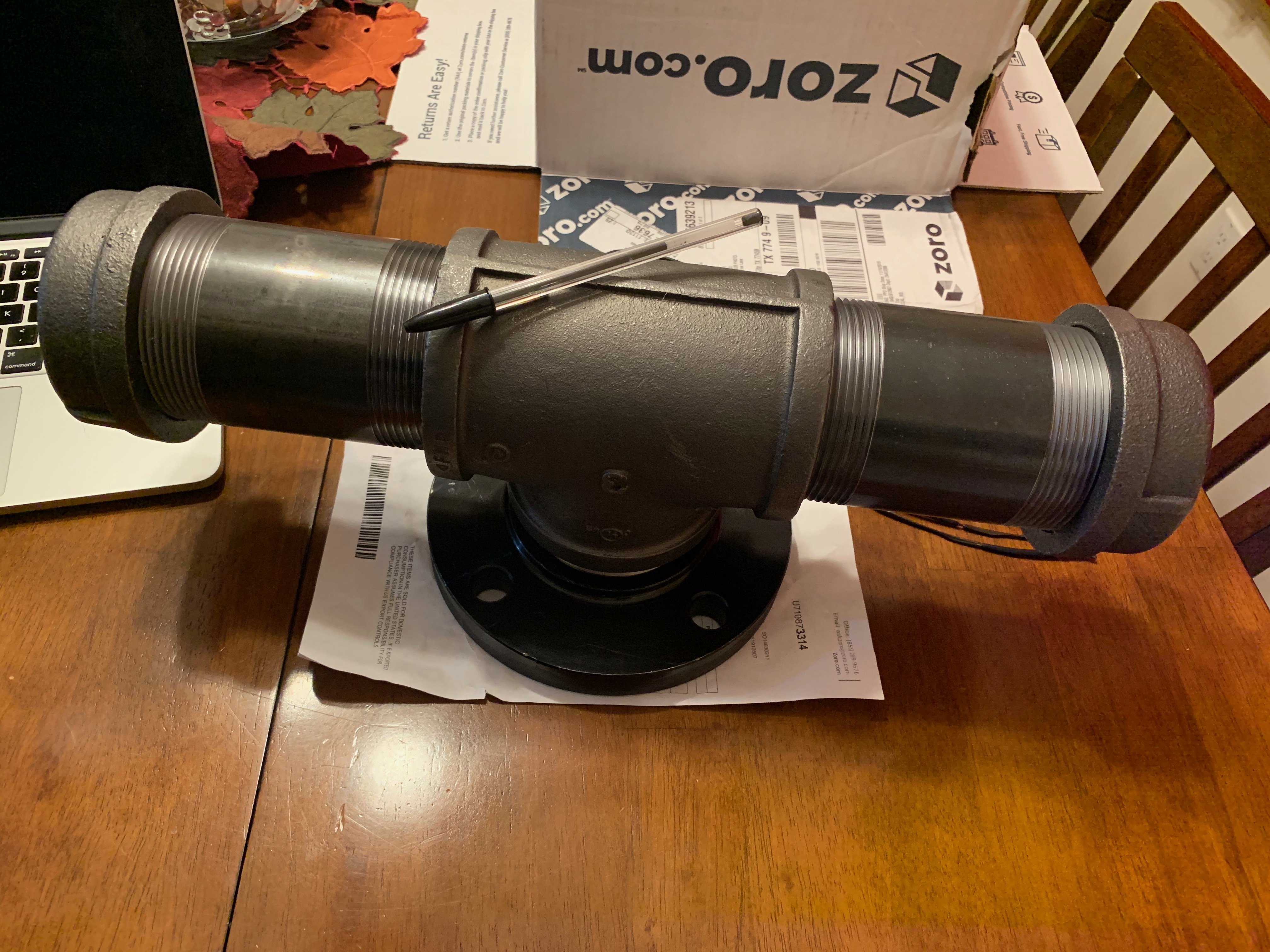
I decided that a piece of tube between the flange and the T was unnecessary so I just welded the two together with four big fat tack welds. I’ll come back later and fill the air-gap with RTV and be done.
I also started ‘playing’ with paint. Remember - this is gonna be outside in the elements so it has to be painted to slow rust (no way to eliminate it). Two coats of primer…two coats of hammered -copper…then a dusting of hammered-black to give it some character and make it look old and sorta weathered.
The nice thing is I can go back and forth adding a little more black till I like it…and if I go too dark…just go back and dust it with the copper.
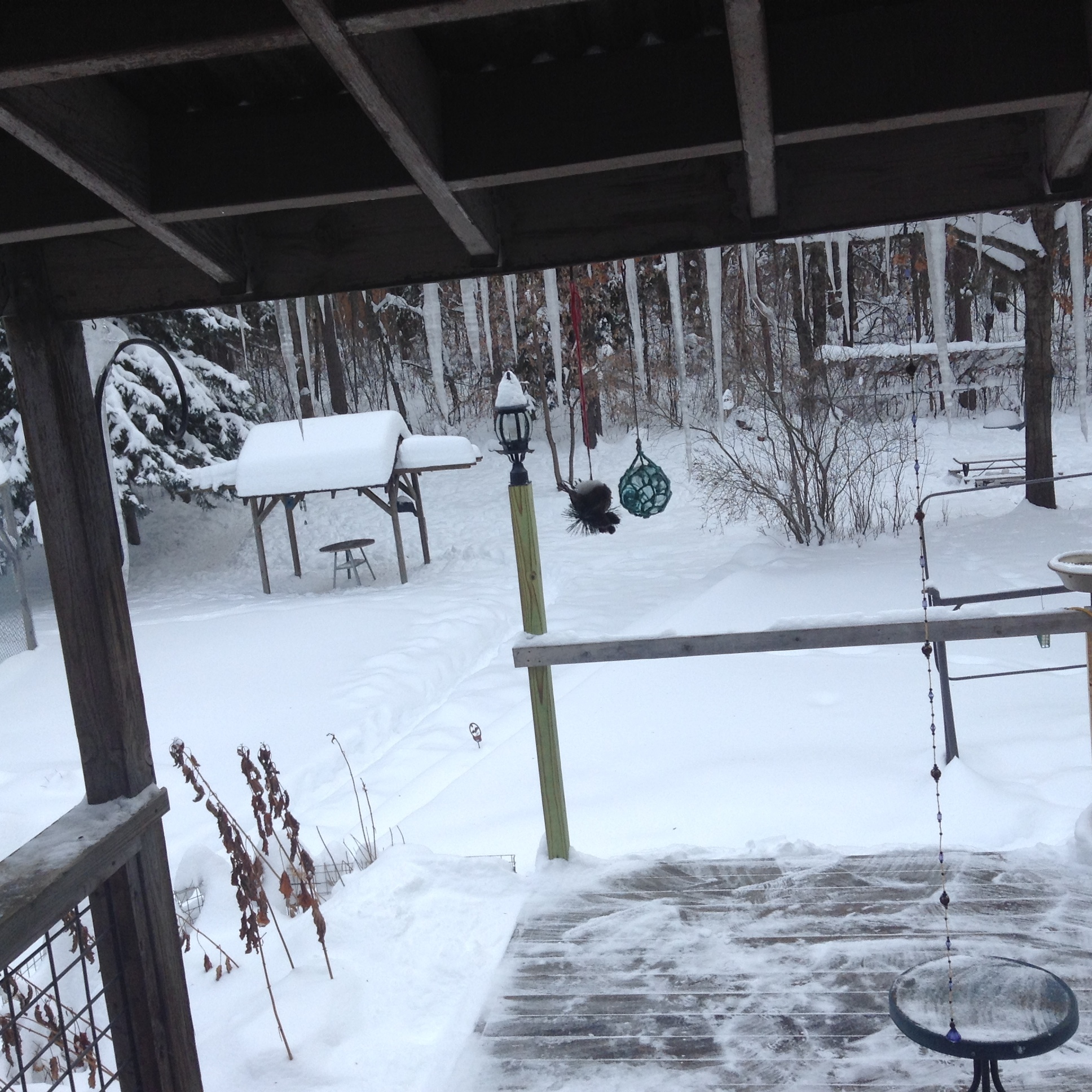
Oh jeez! Ya know, I gripe once in a while about the summer-time heat in Houston until I see something like this. It reminds me to be thankful for what we have (or in this case…for what we don’t have).
Yesterday we had record heat - December 15th and it was 82* and sunny.
Watching paint dry yesterday did not seem very productive so I thought I would play around with making some tap handles.
I had planned to make some unique beer-inspired (aka…drink lots of beer and get inspired) tap handles for each of the 6 faucets. However, after test-fitting the faucets I realized that I really don’t have much room for handles as the faucets are spaced pretty close together.
I don’t have a lathe, but thought about building one like this for my drill-press. But I wanted something more unique than just a turned handle.
I do some other projects for fun with reclaimed wood (cedar fence pickets and/or pallets) and wanted to keep this theme alive. I was going to cut out some simple handles and just figure out how to label them later. Something kinda like this.
So I kept searching. I found a lot of people are doing numbered taps. Most seemed too plain (like these) but some are more bespoke and rustic (like these) . All-in-all, numbers are pretty practical and it’s basically the same thing many micro breweries do. Then - we can compliment the numbered taps with a chalk-board that lists the names, ABV, IBU, etc.
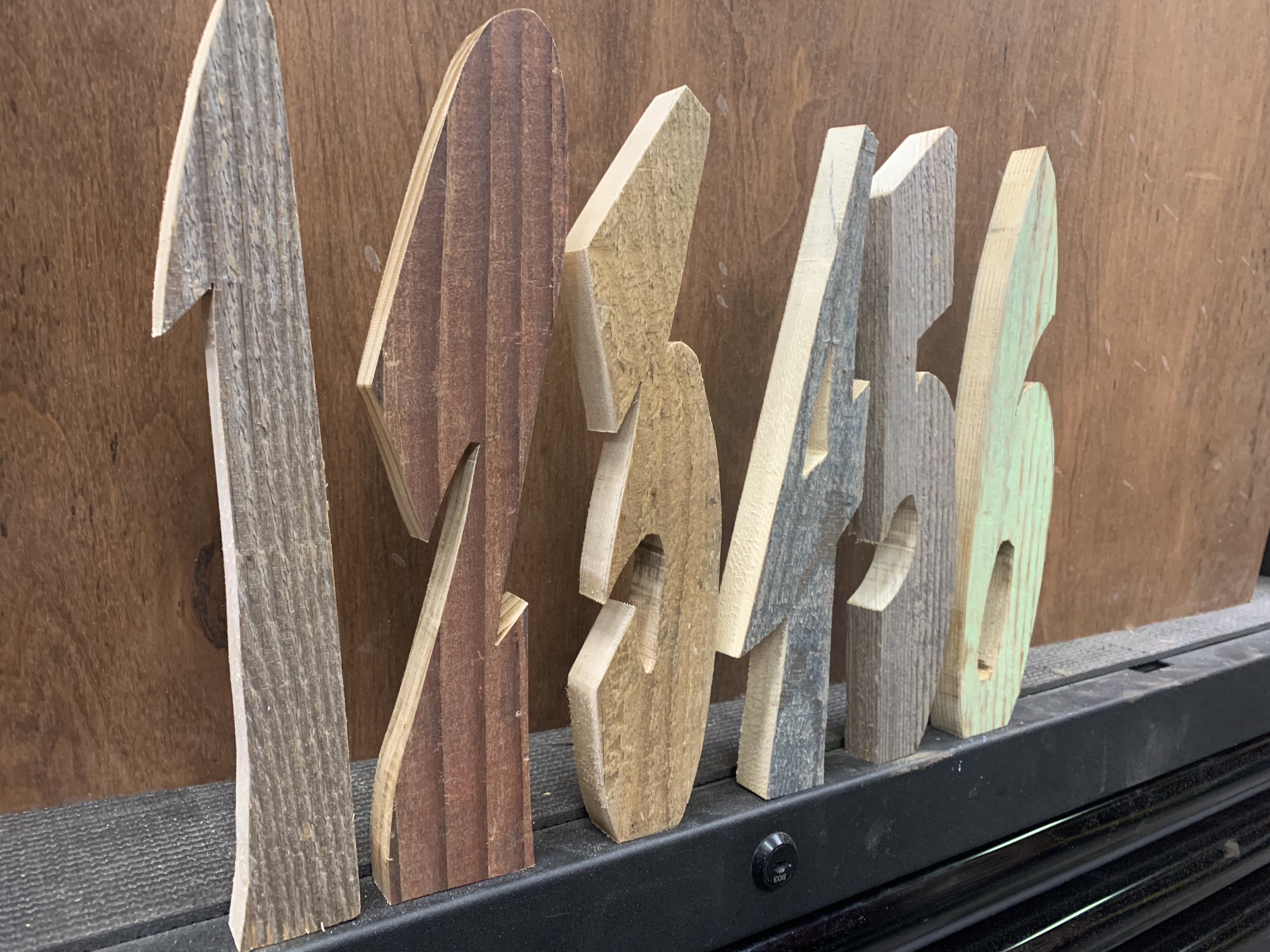
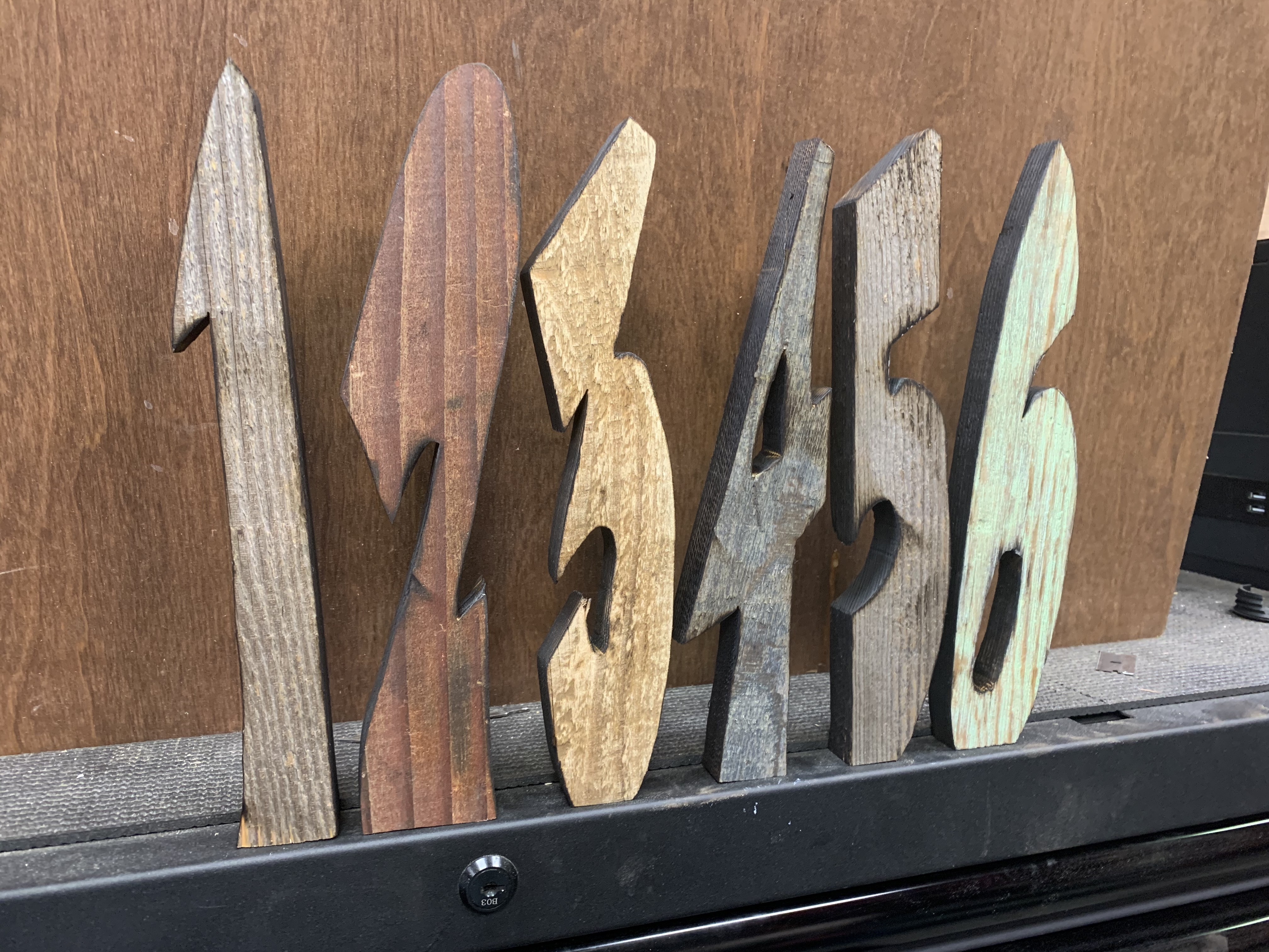
I decided rather than make a wood handle and put a number on it…I would cut the outline of a number directly from wood. I like the numbers in this font and it has the tall/thin characteristics I needed.
I opened an image of the numbers in Photoshop and stretched the image till it was really tall. Then I projected the image onto some heavy paper to use as template.
Next - I transferred the outline onto the wood and cut 'em out.
I modified the letter’s design a bit to create a flat base for the threaded inserts. I found these threaded inserts on Amazon and they end up being less than 60-cents each.
I did some burning with a torch to make the edges (and back side) black.
I still have work to do…need to seal/varnish them and add the thread inserts. However - I’m pretty pleased with how they look. They are the height I wanted and are also narrow enough so they will fit the spacing between my faucets.
 I’m hoping that fan will push enough air and the flexible duct has a high enough R value to keep everything cool.


