New home brewery build

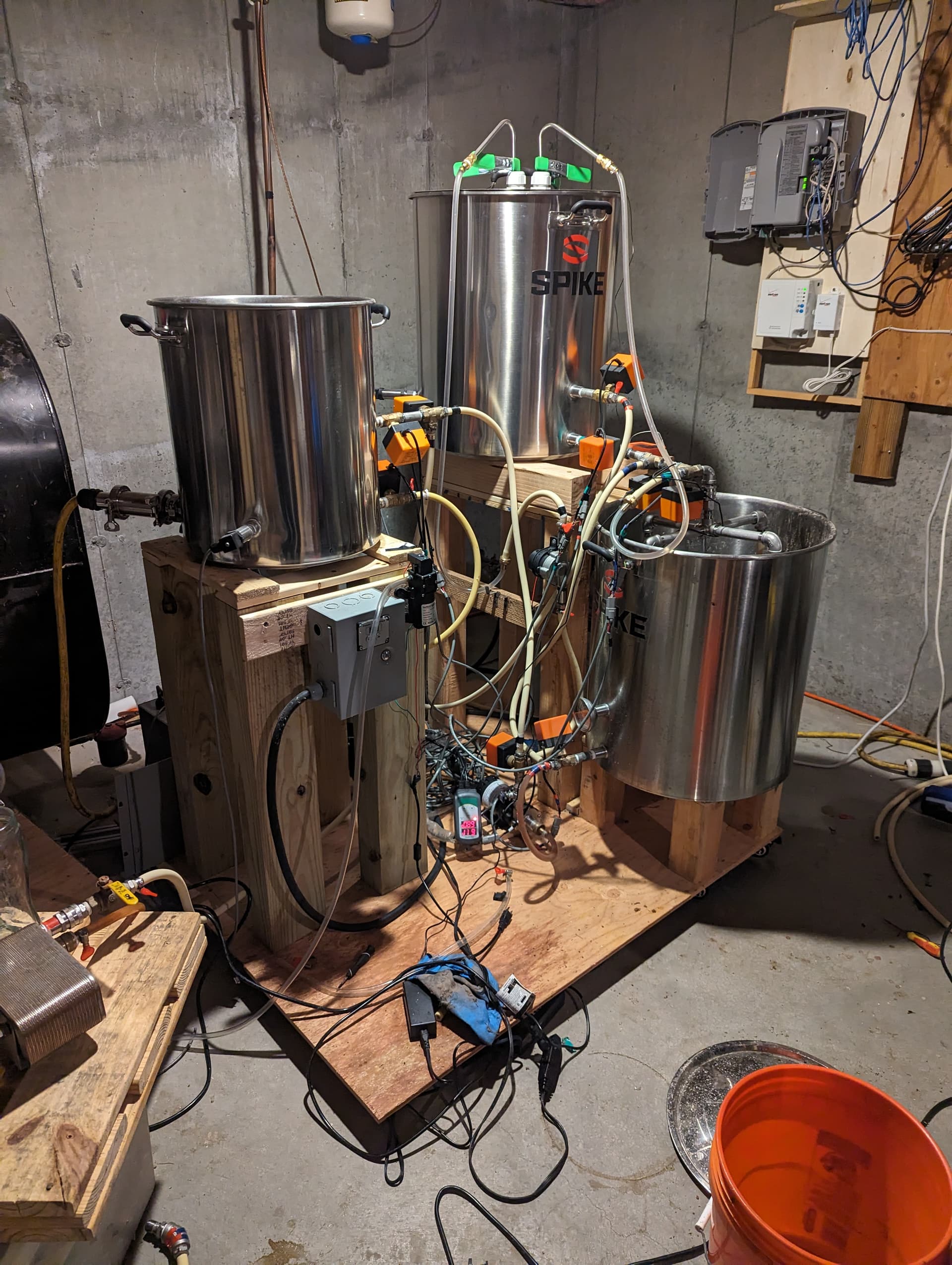
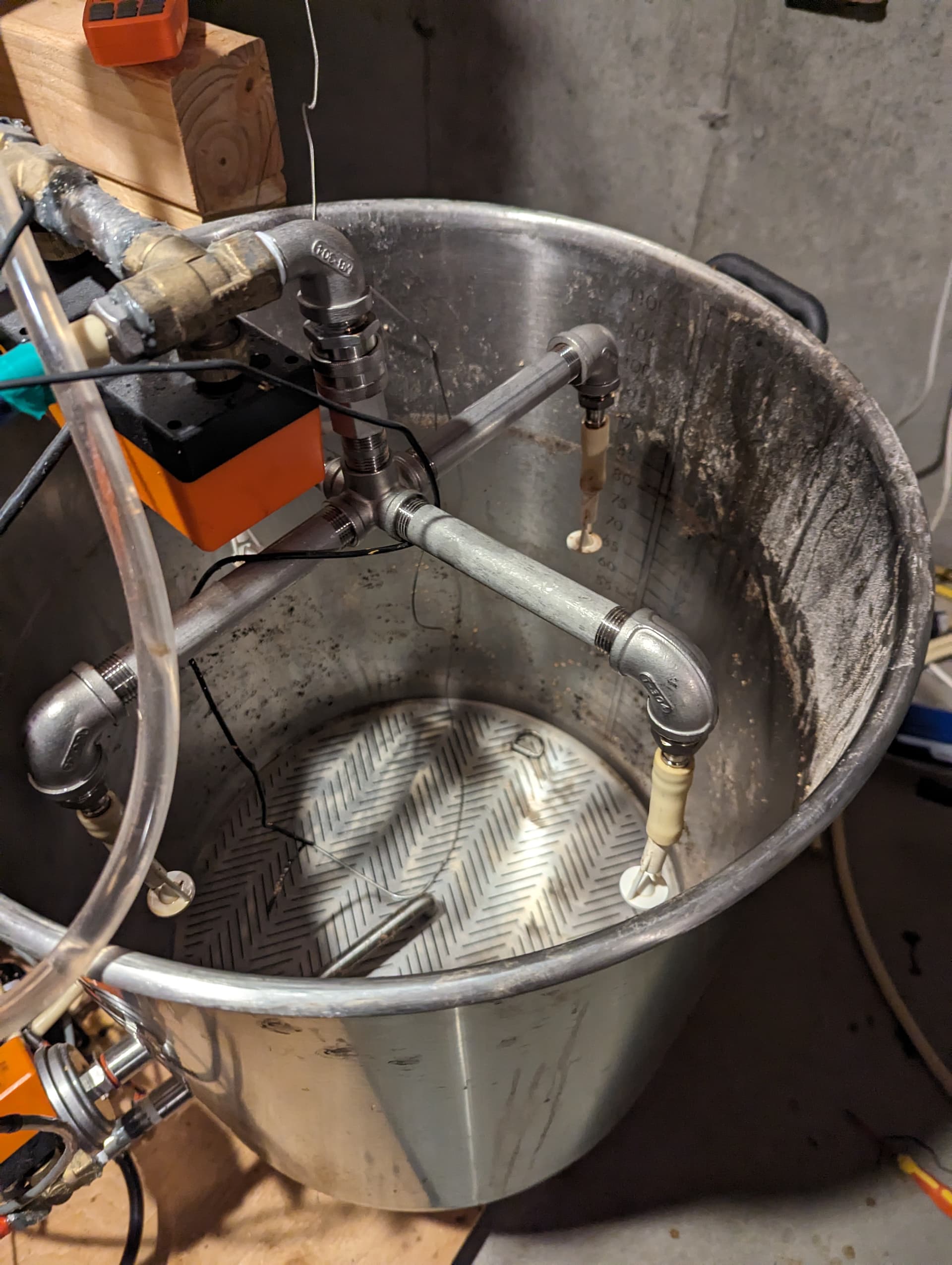
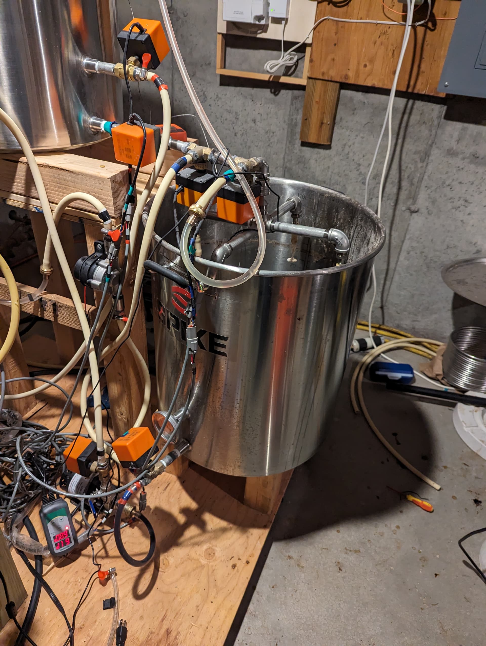
I recently decided to rip apart my custom home brewery, and rebuild bigger and better. I had the old igloo coolers for mash tun and hot liquor tank, and a 15 gallon pot for the boil kettle, with a heater in the BK controlled with PWM and temperature feedback. I wrote the software and wired it all myself, but I would not have been able to brew a 10 gallon batch of my high abv stout in that system. So, I rebuilt! However, I could not locate a big insulated vessel to use as a MT, I decided to change to large SS pot. That would easily lose heat out the sides, so I had to make a HERMS to keep mash at the right temp. So then I needed to make my HLT able to heat up on its own too, so it also needed to change to a SS pot. I will post photos later, but here is what the new system can do and is comprised of

(2) 30 gallon pots for MT, HLT

(1) 15 gallon pot for BK

(2) heating elements, each with their own PWM heat controls

(11) motorized ball valves for routing

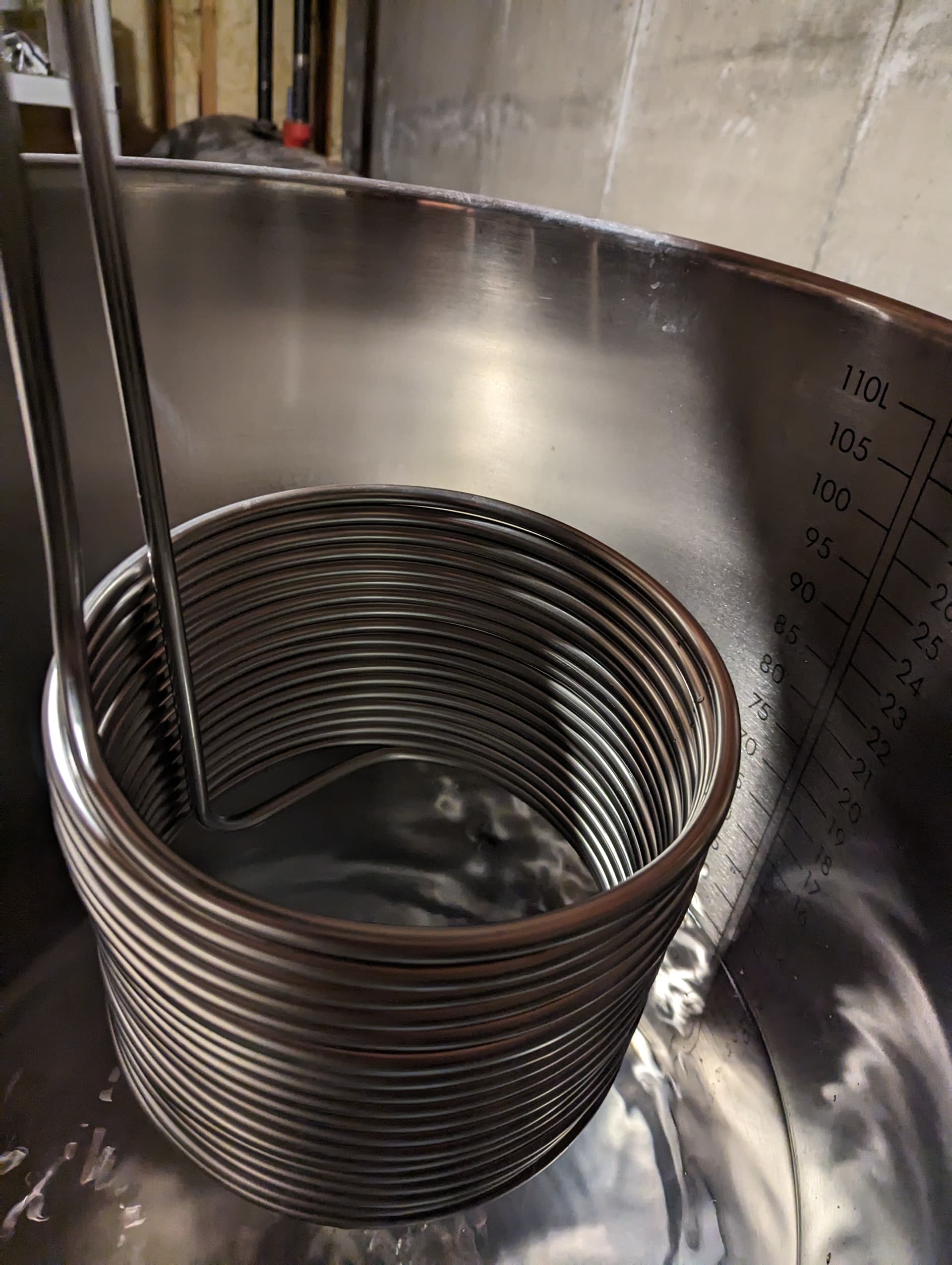
(1) stainless steel immersion chiller used as a HERMS

(2) chugger pumps to move liquid

(1) booster pump to increase liquid “lift” on herms circuit

(1) “home-made” glycol chiller to cool down my plate chiller

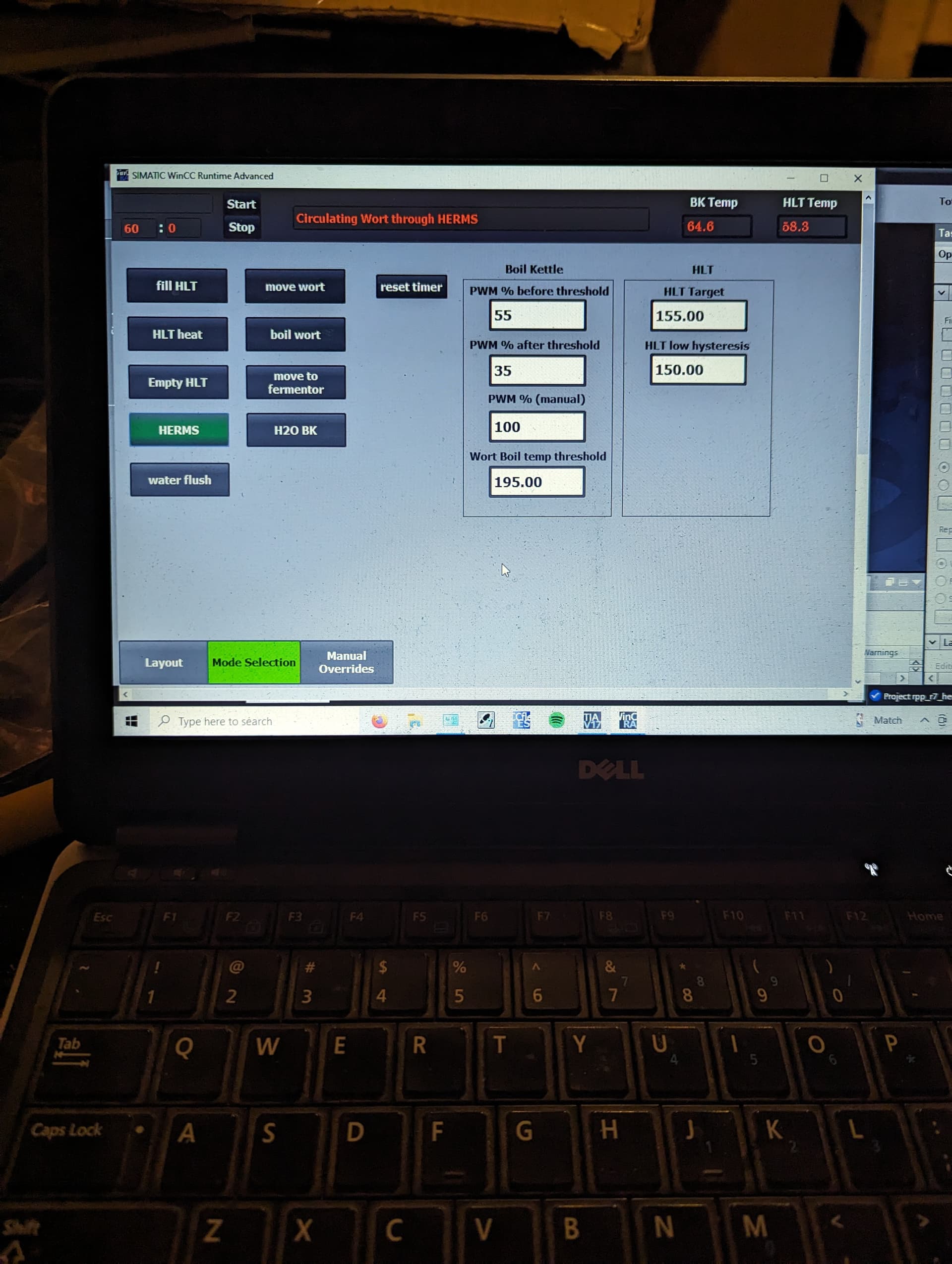
Custom software written by me to control the PLC:

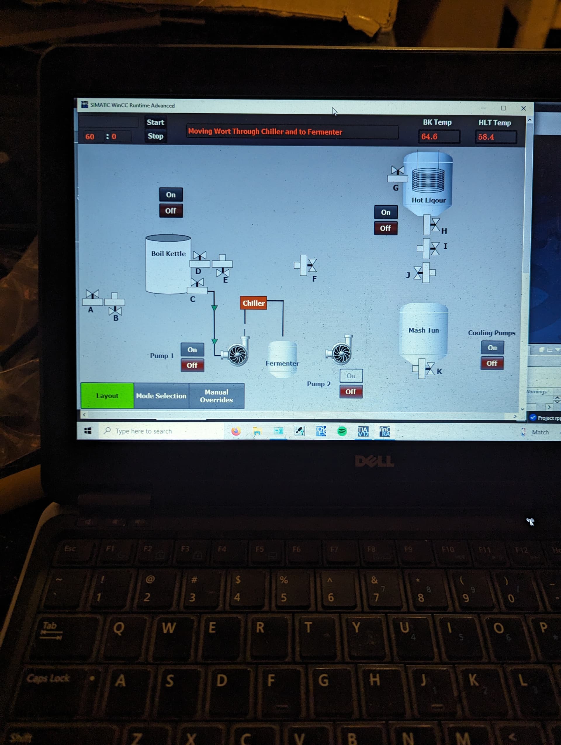
Choose which “step” of brewing I’m in (such as herms, boil wort, sparge heat, etc), all ball valves move to correct orientation. Touch screen will show the route that the liquid will take according to which program is selected.

Click appropriate button on touch screen to activate the proper pumps when needed (can’t use pumps unless the correct “step(s)” of brewing are active).

Click appropriate buttons to activate heaters. Can make temperature setpoints anything you want, including a hysteresis number. Can run each of heaters, independently, at anything from 15% to 100%.

Things it does:

Request water into BK

Request water into HLT

Heat BK for water or wort boil

Heat HLT for strike/sparge

Empty HLT into MT

Circulate wort through HERMS coil

Flush out any remaining wort from herms circuit

Move wort from MT to BK

Move wort from BK through plate chiller to fermenter

3 Likes

That sounds like quite a set up! Any pictures?
Sneezles61

I’ll have some photos tomorrow. Be forewarned, it’s a MESS right now! I just did a large brew, and I’m letting everything dry out before I start to scrape it all off and clean fully. Don’t judge me on the gross mess

1 Like

Would love to see pics as it comes together!

I’m already impressed and also waiting on photos.

Overall system (on a platform that is mobile)

Mode selection screen

Layout + routing

HERMS inside HLT (sticks through the lid)

MT with homemade sparge arm

HLT feeding into MT

Not the prettiest setup, I want to replace all the tubing with actual SS pipe someday. And like I said, everything is messy thanks to a recent brew. But overall, I love the functionality and capabilities. And since I designed, built, and wrote the program, I can customize further whenever I want.

1 Like

Looks good! Nice to see some wiring as confusing as my own :wink:

All those orange cubes then must be the motorized valves? Are they then operated by a SSR? That is a very nice, big system.
I thought about HERM’S when I built mine… but then waffled into a simpler rig. I haven’t any knowledge how to make a computer do all the thinking and monitoring… You are very talented.
Sneezles61

Yes each orange cube is a motor to activate the ball valve. They are being controlled by a PLC, using a digital output to activate a double-throw relay. One throw is to open the valve, the other throw is to close the valve.

Each heater is connected to their own SSR. The PLC generates a pulse that activates each SSR. I then control the pulse width using PWM to get the heater to run at specific %, which allows me for better heat control. Each heater has a dedicated Thermocouple for feedback.

I appreciate the kind words. I have worked in automation for my entire career, so it was nice to finally apply my skills to a fun system for myself.

2 Likes

Yea the wiring is a mess. I color coded everything, so each valve has a color on it that matches the color on a specific cable. Same thing with each pump as well. Every cable ends in a quick connector, whether it’s a 115vac plug or just a 3-pin connector for the ball valve power. That allows me to disconnect them if I need to move stuff around for customization or cleaning. It’s ugly, but there’s a method to my madness!

My next build is to possibly create a hop dispenser that would eject hops into the boiling wort according to the hop schedule. I also want to see if I can make the valves work on wireless controls. There would still be wiring involved, but I could hide them much better and make it all look neater.

There is a small brewery that has an auto grain assembly. The grain is weighted out in a separate are then goes overhead on a cable. It is dumped into the ton and an automated mash paddle. It is quite simple. The grain doesn’t drop in a lump but small containers that somehow hits a bar and tips in then comes around for more. Someone had fun. It was built behind a glass window so could watch from the tap room. It was kinda like Santa’s workshop. Those clever elves brewing beer, who knew

1 Like

That’s some amazing stuff. Great knowledge to have!

I have designed (but haven’t built yet) an auto feed system that would take grain from my mill and feed it into my mash tun. That way all I’d need to do is dump the grain into the top of the mill and then I’d be all done lifting anything until cleanup.

What I really need is a deep basin sink installed. Throwing stuff outside and using the garden hose is annoying.

1 Like