I need help wiring a honeywell t7079a 1046 single stage temperature controller- the instructions can be found here (though these are for a two-stage controller):
I also included a picture of the relevant circuit board. There are 6 screws, and from left to right they are:
NC1, COM1, NO1, 240V, 120V, COM.
I have a three-prong extension cord I plan to use- can someone tell me which wires from the extension cord go to which screws on the controller, and if any jumpers between any of the screws are necessary? I’m fine wiring things when I have instructions- I did an analog Johnson temp controller because someone here posted the picture of what to do. But I have no idea what to do for this one, and I can’t find any mention of it on the web. Thanks!!
For cooling apps you want to hook the output up to NC1 and Com1 on the left. The relay is closed until it reaches it’s set point then it opens the circuit.
Input is 120V and COM on the right. Wire nut the ground wires together.
The power light comes on, and the stage light comes on when the temperature is above the set point, but the fridge never turns on (the fridge works just fine when plugged directly into an outlet). From the part of the extension cord I cut with the receptacle, I had the live wire in NC1, neutral in COM1; on the 3-prong side, I had live in 120V, neutral in COM. I tried reversing these, too, but that didn’t work (live=COM1, COM; neutral=NC1, 120V). I also tried switching it around, so that the receptacle went to the 120V, COM and 3-prong went to NC1,COM1, but all that did is trip the circuit.
Is there something I am missing that I should do or check? Or do I perhaps have a bum controller? Thanks again for all the help!
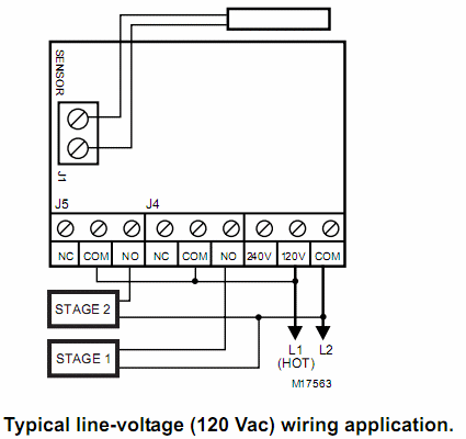
I never looked at the link in your original post and assumed the 120V and neutral were fed through the input and switched in the control to output. After looking at it I see you need to feed 120V to com1 on the output then it gets switched to either NC1 or NO1. Ignoring stage2 it would be wired like this except the output will be on NC1:
The neutral (L2) will be connected outside the controller.
The input labeling is kind of confusing, it should be marked 120V and N or L1 and L2
Thanks for all the help. For anyone else who is using this controller, he wiring is the same as the Johnson A419 digital controller, and the wiring diagram posted here will work:
My fermentation chamber is now complete and already in use, which is quite nice given the way this summer is going in Iowa (my basement is getting >75F). Thanks again, Glug Master!